Last edit: 26/07/2023

The guard-rail is necessary and mandatory when fall risk from height higher than 500 mm is present, or if the distance between the walking platform and a neighbouring structure (machinery or wall) is greater than 180 mm. The standard specifies that the guard-rail minimum height shall be 1100 mm, with handrails lower than 1100 mm (parallel to the walking line). A baseboard or toe-plate shall be provided when the gap between the platform and neighbouring structure is greater than 20 mm.
Fall risk shall be reduced using knee rail (maximum distance 500mm) or vertical uprights (maximum distance 180mm); in the case of interrupted guard-rail the clear space between the two stanchions must be between 50 and 120 mm (between 50 and 80 mm in the case of segments at rounded ends).
How to design guard-rails for stairs and step ladders

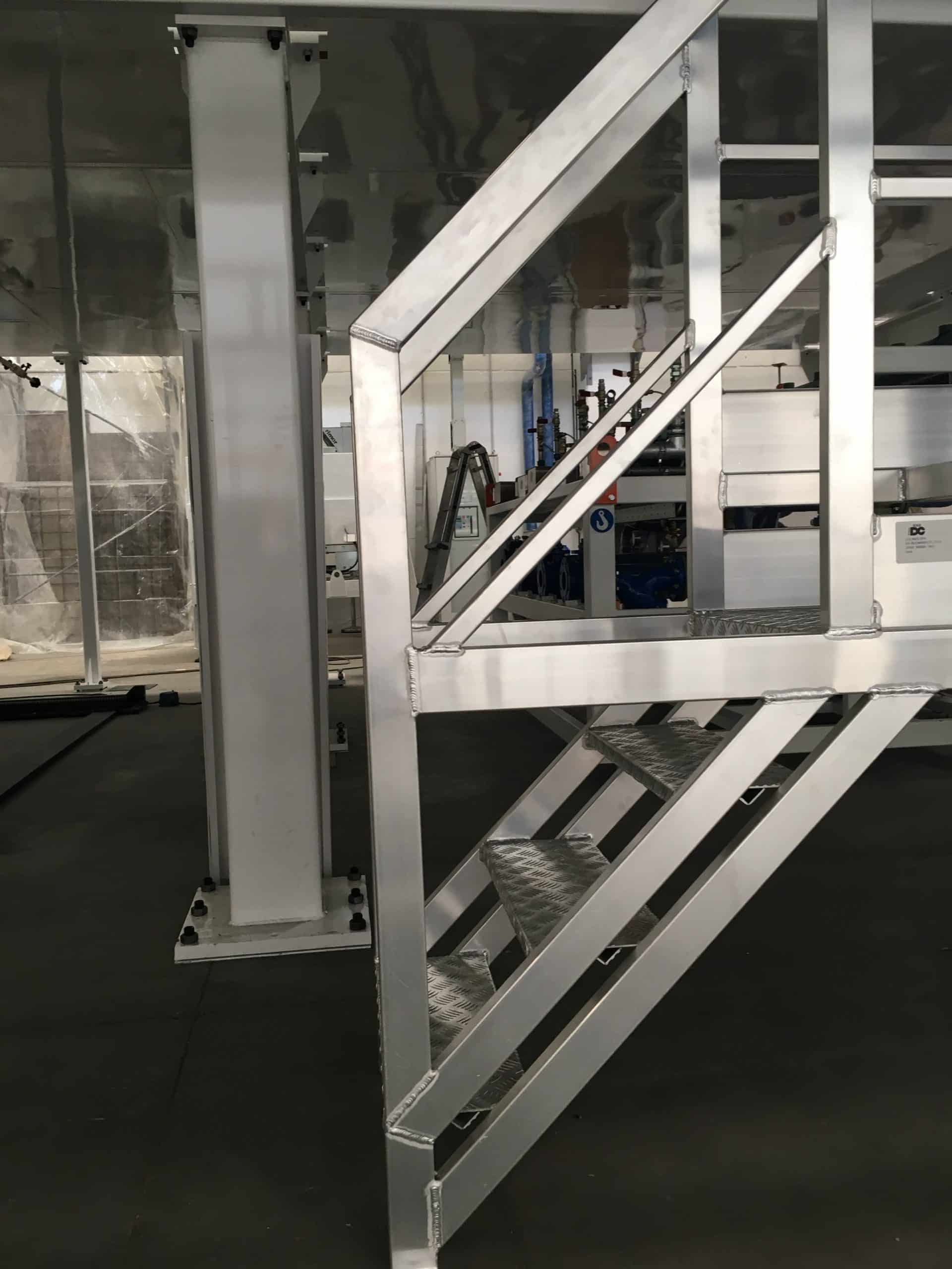
The standard also covers design of guard-rails for stairs and step ladders, mandatory for falling height greater than 500 mm or in presence of gaps between walking platform and a neighbouring structure (machinery or wall) wider than 120 mm. The guard rails must have a knee rail and a handrail on both sides, prioritizing non-interrupting rails. The handrail height shall be between 900 and 1000 mm, measured from the nose of the step; the handle shall be clear of obstacles within 75 mm, with a diameter between 25 and 50 mm.
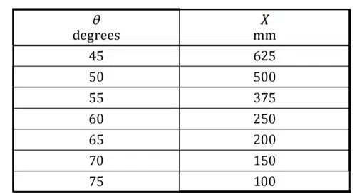
For step ladders, the guard-rail start shall not be higher than 1000 mm measured vertically from the bottom of the ladder, the "X" distance value between the handrail and the supporting structure varies according to the slope of the ladder.
Design of the access gate
Any access gate shall meet the requirements of the adjacent guard-rails, except for the toe plate which is not required. Self-closing gates shall be held in position without being locked, designed to open easily onto the platform or floor and close against a firm stop to prevent accidental falls.
Verification of safety requirements
In addition to the verification of steps failure resistance, the standard dictates a similar verification for the deformation "f" of the guard-rail. As shown in the below image, the test (which can be replaced by a theoretical calculation) shall be carried out at a guard-rail element with three stanchions, applying transverse load at central stanchions (Position 1) or between the central and the lateral stanchions (Position 2). The guard-rail is preloaded with a load Fp= 75N/m *L (L is distance between the vertical stanchions) for one minute, after which the discharge takes place.
During the test, a load Fu= 300 N/m*L is applied, and the resulting deformation shall not be greater than 30 mm. Once the deformation is measured, the load is increased to Fs= Fu*γ (γ is coefficient of the material, equal to 1.75 for steel and aluminum alloys). Once the guard rail is discharged, the deformation must be [14122-3:2016 – § 8.2.3]:
1. <3%*H for load applied at the central stanchion (Position 1).
2. <3%*L for load applied between the central and the lateral stanchions (Position 2).
