Last edit: 23/10/2024
In Category 2, both Basic and Well-tried safety principles must be followed.
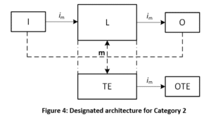
It is a single channel architecture with the monitoring of each subsystem done, in its most general form, by an external unit called Test Equipment. In case a fault is detected, the TE signals it to the “outside world” thanks to an output: the OTE.
Hereafter how the Safety-related block diagram looks like.

Keys:
- Im represents the interconnecting means, typically electrical wires
- I represents the Input
- L represents the Safety Logic; it can be also a wire or a Safety Module (non-programmable) or a Programmable Logic.
- O represents the output; it can be a contactor or a solenoid valve, for example
- m represents the monitoring done by the Test Equipment (TE)
- OTE is the output of the test equipment.
Compared to a Category 1, you can notice the presence of a Test Channel, made of a Test Equipment or TE and of its output, the OTE or output of the Test Equipment.
Using a Category 2 architecture, all performance levels, except PL e, can be achieved.
Also, for this category, figure 4 shows a subsystem and not necessarily a full Safety-related control system.
In Category 2, the fact that PL d can be achieved, a certain level of Diagnostic Coverage (at least Low) needs to be present: the functional channel needs to be tested at suitable intervals by the test equipment. The check of the safety function shall be performed prior to the initiation of a hazardous situation, for example:
- Prior to the start of a new cycle and/or,
- Prior to the start of other movements and/or,
- Immediately upon a demand of the safety function and/or,
- Periodically during operations, if the risk assessment and the kind of operation shows that it is necessary.
Any check of the safety function allows its operation, if no fault is detected, or it generates an output (OTE), if a fault is detected.
It is important to highlight that, in case of PL d, the OTE (Output of the Test Equipment) must initiate a safe state, which is maintained until the fault is cleared. On the other hand, in case of PL c, a safe state is not required and it would be enough to provide a warning.
[EN ISO 13849-1] 6.1.3.2 Designated Architectures – Specification of Categories
6.1.3.2.4 Category 2.
[…] For PLr d the output (OTE) shall initiate a safe state that is maintained until the fault is cleared.
For PLr up to and including PLr c, whenever practicable the output (OTE) shall initiate a safe state that is maintained until the fault is cleared. When this is not practicable (e.g. welding of the contact in the final switching device) it may be sufficient for the output of the test equipment OTE to provide a warning.
The Diagnostic Coverage (DCavg) of the functional channel shall be at least Low. The MTTFD of the Functional channel shall be low‐to‐high, depending on the required performance level (PLr).
In any case, measures against CCF are applicable.
Of all the four, Category 2 is probably the most difficult one to understand: let’s try to clarify its usage and understand the reasons of its limitations. For that, we need to go through its Markov Modelling. We will do it in the next article, the last one for 2024.