Last edit: 27/02/2026
Continuity of the protective bonding circuit – inside control panels

The IEC 60204-1 requires the Verification of the continuity of the protective bonding circuit both inside and outside of the Control Panels.
In general, the protective bonding circuit is needed non only to earth Exposed Conductive Parts but also in the following situations:
- To bond Extraneous Conductive Parts,
- To connect the common pole of a control transformer
- To connect the sensitive electrical equipment to the PE or to the FE terminal
- and, as already stated, to earth Exposed Conductive Parts.
All those connections must be tested to verify they are effectively in place and properly done. The way to do it is detailed in the standard:
[EN 60204-1: 2018] 18.2.2 Test 1 – Verification of the continuity of the protective bonding circuit
The resistance between the PE terminal (see 5.2 and Figure 4) and relevant points that are part of the protective bonding circuit shall be measured with a current between at least 0,2 A and approximately 10 A derived from an electrically separated supply source (for example SELV, see 414 of IEC 60364-4-41:2005+AMD1:2017) having a maximum no-load voltage of 24 V AC or DC.
The resistance measured shall be in the expected range according to the length, the cross sectional area and the material of the related protective conductors and protective bonding conductor(s).
The test can therefore be done following the same procedure as the one used outside the panel; the issue is that the value obtained is usually very small and some instruments may struggle with the measurement.
IEC 60204-1 allows the use of criteria from IEC 61439-1, when those are deemed applicable:
[EN 60204-1: 2018] 4.2.2 Switchgear
In addition to the requirements of IEC 60204-1, depending upon the machine, its intended use and its electrical equipment, the designer may select parts of the electrical equipment of the machine that are in compliance with relevant parts of the IEC 61439 series (see also Annex F).
The Test can therefore follow what IEC 61439-1 states for the earth continuity onside an electrical panel.
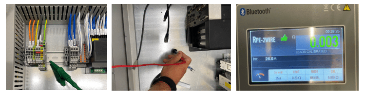
[IEC 61439-1:2021] 10.5.2 Effective earth continuity between the exposed-conductive-parts of the class I assembly and the protective circuit
It shall be verified that the different exposed-conductive-parts of the assembly are effectively connected to the terminal for the incoming external protective conductor. Verification shall be made using a resistance-measuring instrument that is capable of driving a current of at least 10 A (AC or DC). The current is passed between each exposed conductive-part and the terminal for the external protective conductor. The resistance shall not exceed 0,1 Ω.
The measures have to be taken from all Exposed conductive parts inside the panel and the Earthing terminal, where the panel is connected to be itself earthed. For example the backplate, the doors, the Power Drive System metal enclosure etc.
Continuity of the protective bonding circuit – outside control panels

The IEC 60204-1 requires the Verification of the continuity of the protective bonding circuit also outside of the control panels: what is commonly indicated as “the filed”.
[EN 60204-1: 2018] 18.2.2 Test 1 – Verification of the continuity of the protective bonding circuit
The resistance between the PE terminal (see 5.2 and Figure 4) and relevant points that are part of the protective bonding circuit shall be measured with a current between at least 0,2 A and approximately 10 A derived from an electrically separated supply source (for example SELV, see 414 of IEC 60364-4-41:2005+AMD1:2017) having a maximum no-load voltage of 24 V AC or DC.
The resistance measured shall be in the expected range according to the length, the cross sectional area and the material of the related protective conductors and protective bonding conductor(s).
The instrument must inject a current between 0,2 A and 10 A, however higher currents can be used, since the higher the test current the more precise is the measurement. All exposed but also extraneous contuctive parts have to be verified.
“The resistance measured shall be in the expected range…” means that the value measured must be compared with the “theoretical” value calculated using the IEC 60228 standard.
Parallel resistances
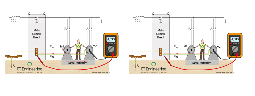
One of the issue when doing the measurement is the presence of parallel resistances. In the drawing hereafter, while measuring the protective bonding circuit of M2, meaning the value of resistance RPE2, in reality, the parallel resistance RPE2// RPE1 is measured.
In order to do a more precise measurement, the PE2 conductor can be disconnected from the Control Panel copper bar (or earthing terminal), before doing the measurement, like shown in the drawing on the right.
Despite that makes sense, it is not required by the standard!
The standard accepts the fact that, during the measurement, parallel resistances are taken into consideration.